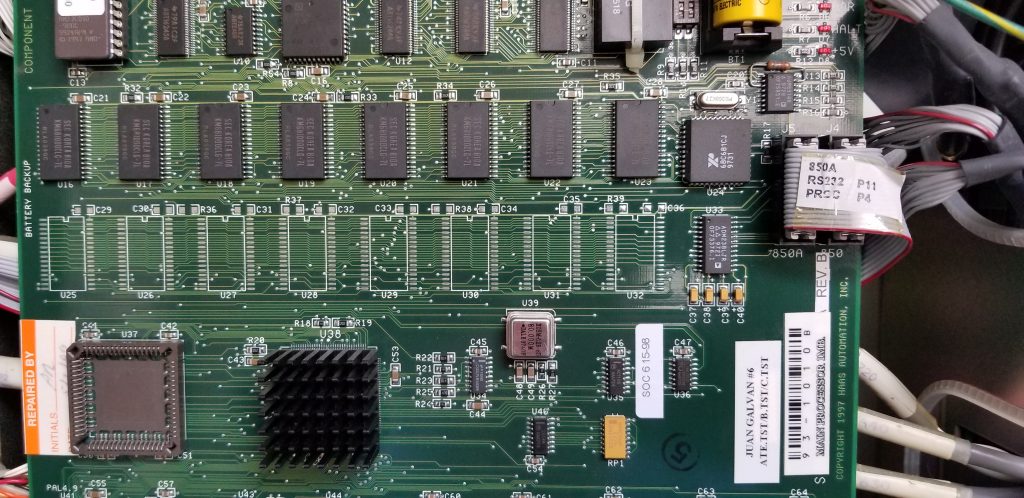
This page is my attempt to document my findings in regard to troubleshooting the serial communications problems we’re having with the HAAS VF-3 milling machine at i3Detroit. This work was done on Friday, September 13th.
For background info, the i3Detroit HAAS started experiencing intermittent RS-232 comm problems in the spring of 2019. The serial port is the only means of transferring g-code programs to the HAAS. Without which, large g-code programs generated by CAM software become impossible. A typical g-code program, generated by CAM software, will have many thousands of lines of code.
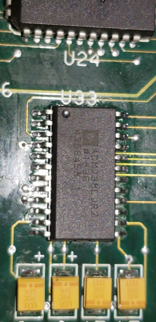
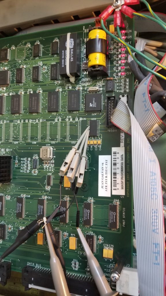
A “quick” fix was attempted by replacing U33 on the processor board. U33 is a RS-232 transceiver chip. Here is a link to a replacement chip at Mouser. This chip provides four drivers and four receivers. The chip also has a built-in dc-to-dc converter (charge pump) to generate the +/- 10V voltages need from a single 5Vdc supply.
Besides U33, all four surface mount caps that are part of the charge pump circuit were also replaced with new. These four caps are designated C37 thru C40 on the board.
While the replacement of U33 and caps seem to have gone well, the intermittent comm problem only got worse!
Just to make sure, the +5V, +12V, and -12V power supply rails were checked. The 5V rail has some noise (about +/-250mV) but not too bad. The +12 and -12V rails look fine.
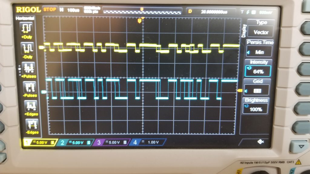
Next, I looked at the actual Rx and Tx signals on the scope.
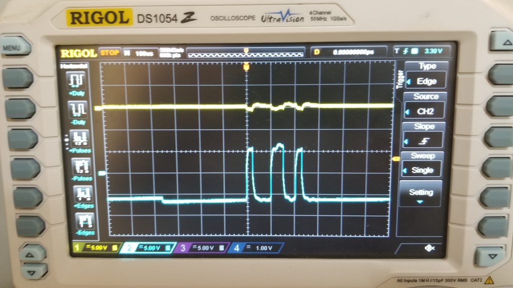
To look at the basic Rx signal I disconnected the ribbon cable right at the processor board. So, this is basically shows the signal coming from the USB dongle plugged into my laptop (no HAAS involved). Signal looks good. A nice 10V swing centered around ground.
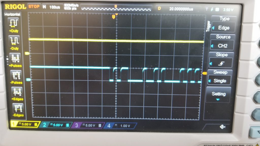
The plot above shows a crappy Tx signal coming out of the HAAS! This must just be on the edge of communicating. The HAAS Tx signal is maybe +/- 2 Volts. Way below the +/- 5V lower limit. And sure enough, communications soon stop working while I was working on the machine.
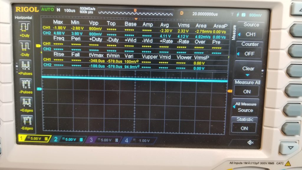
Next, I just measured the charge pump voltages. Both while communicating and static. The results are the same. V+ averages 4.11 volts and V- averages -2.3 volts. Well below the +/- 10 volts they should be.
Just as a check, I probed both Rx and Tx on the TTL side of the Transceiver. No problem.
So, bottom line, seems there is something very wrong with the charge pump in the NEW transceiver chip. I think it very unlikely there is a problem with the new chip or replacement SMD caps. However, I’m also at a loss to explain the problem either. My stretch guess would be HAAS is using the +/-10 volts from the charge pump for other purposes (like suppling +/- voltages to an op-amp). However, the processor board already has a +/- 12 volts supplied to it. So why use the charge pump? Could pull the board and trace circuit board traces to know for sure.
A crappy answer to these problems would be to remove U33 and graft on a separate transceiver. Would only requiring tapping into the TTL signals for Rx and Tx after U33 had been removed. Not the best answer but it should make the HAAS run again in lue of finding the real problem – which escapes me.