Components
This section provides detailed information about the various components that make up the Looper system. Understanding these components is crucial for effectively utilizing the Looper and ensuring seamless integration with your CNC machines. In the following sections, you will find comprehensive descriptions, specifications, and functionalities of each component. Whether you are setting up your Looper for the first time or troubleshooting an existing setup, this guide will serve as a valuable resource.
Explore the details below to learn more about Looper’s different components and how they contribute to enhancing your CNC operations.
Front-Side Components
List Button
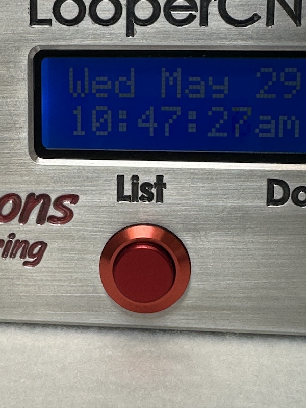
This red button, located off-center to the left on the front face, allows for users to view log files that have been collected by the CNC machine. Users can scroll through previous log files using the “Select” knob. When you are done viewing the log files, press the “Select” knob in once to return to the Looper Home Screen. If no actions are taken within 30 seconds of pressing the “List” Button, the Looper will time out and return to the Looper Home Screen.
Download Button
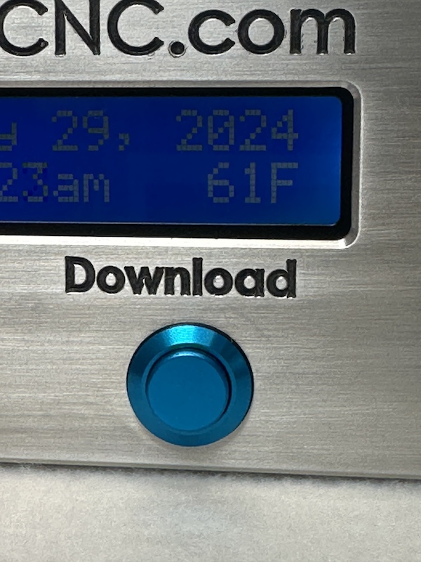
This small blue button, positioned off-center to the right on the front face, initiates the download of programs to the CNC machine.
Note
In order to upload a file to the CNC machine, the following steps must be taken:
The CNC Machine must be on the “LIST PROG” screen in order to receive a file from the Looper Box.
After navigating to this screen, put the CNC cursor on the “ALL” button at the bottom of the list of programs.
Select the “RECV” key on the CNC control panel.
Finally, select the “Download” button on the Looper Box.
The program will then be uploaded from the Looper Box to the CNC machine.
More information can be found in the “File Upload” section of the manual.
Select Knob
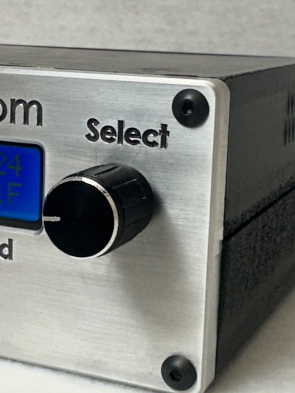
The knob on the front of Looper is an encoder style knob which can freely turn both clockwise and counter clockwise. It is used primarily to scroll through messages. The knob can also be depressed which is used to escape out of operations.
Note
Depressing the knob for several seconds will cause Looper to abort and restart the software application. By continuing to hold the knob depressed for longer, 10 seconds or more, Looper will go into shutdown mode. Do this before unplug the power feed. This prevents the risk of the solid-state flash disk from getting corrupted.
Power Indicator LED
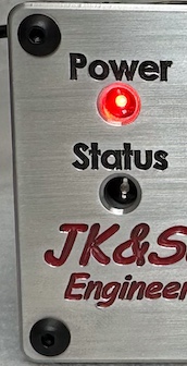
A red pulsating light indicates that the Looper CNC Box is properly powered. If no light is showing, ensure that power is properly connected and the Power On/Off Switch is toggled to the On position.
Status Indicator LED
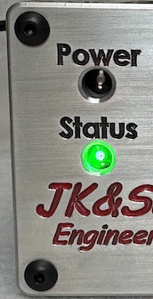
The status indicator is used to show when the Looper Box has received new data. The status indicator will display a green pulsating light when new information has been received. The Status Indicator light will turn on when a new files is uploaded to the Looper Box or when Log Files from the CNC machine are downloaded to the Looper Box
Back-Side Components
On / Off Toggle Switch
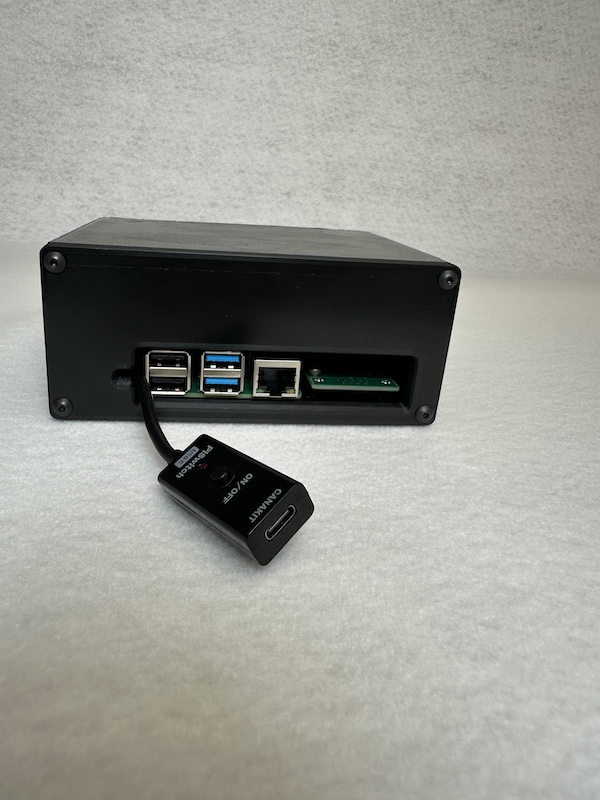
Located at the rear of the box, this switch powers the device on and off. When connected to a power source, pushing the On/Off Button the Looper Box will power on and off.
Warning
Warning: Potential File Loss
Do not toggle the Off Switch without correctly performing a powerdown cycle. Failing to follow the proper powerdown procedure may result in data loss, equipment damage, or operational malfunctions. Always ensure you follow the recommended powerdown steps to safely shut down the Looper system.
USB Ports
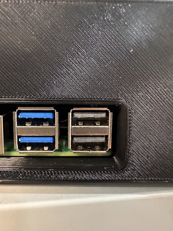
Looper features two USB 2.0 ports (black) and two USB 3.0 ports (blue) for connecting external devices.
Ethernet Port
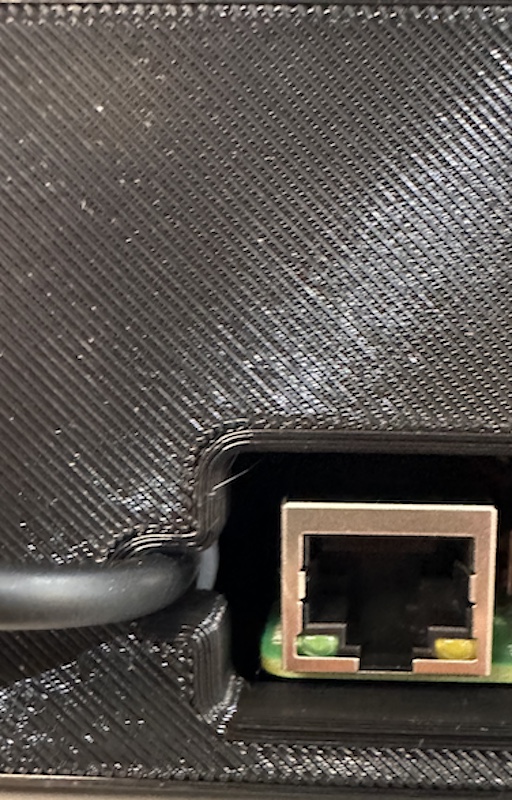
This port provides a network connection for accessing the CNC machine wirelessly.
USB-C Power Supply Cable
Looper operates with a standard 120V AC power from a wall outlet into a stable 5V DC output with a current of 3.5A, using a USB-C connector for secure and straightforward connection. Featuring built-in protections against overvoltage, overcurrent, and short circuits, the power supply guarantees both safety and longevity for the Looper device.